Tower Unite Workshop Playermodel Guide
This guide assumes you are importing a model with little 3D knowledge, but it's recommended you have some previous experience with 3D software and Blender.
This is not a tutorial on how to create and rig model from scratch. This guide assumes you have a previously rigged character model.
More detail is listed within various links throughout the guide that’ll jump to the relevant information.
After clicking a hyperlink, you can press the back button on your browser to jump back to where you were.
There are three main sections of this guide:
Player Model Guide
If this is your first time using Blender, I'd highly recommend browsing (or at least skimming) the last 2 sections, as they go over the terminology, controls, UI, and other important information.
Prerequisites
You will need:
- The v3 Workshop .blend file
-
Blender version 4.0 or higher
- Older versions of Blender are likely usable (at least above 2.8), but are unsupported, untested, and generally unrecommended. You may get an error saying "file written by newer blender binary, expect loss of data", typically you can ignore this.
- Other 3D software may still work but is both unsupported and not recommended.
-
A pre-rigged character model.
- If exported from an existing source, you only need the mesh with vertex groups (mesh data for rigging to the skeleton), the skeleton itself isn't necessary. (but useful for adjustments)
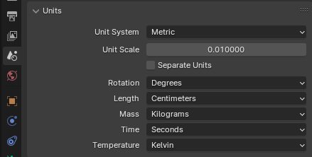
The v3 rig .blend file includes these project settings by default, you can find these sections in the Properties Menu.
SCENE PROPERTIES
Unit Scale: 0.01
Length: Centimeters
Scene: +Z Up, -Y Forward
Bone Roll: Global +Y
OUTPUT PROPERTIES
(if exporting custom animations [not supported yet])
Frame Rate: 30 fps
Player Model Guide
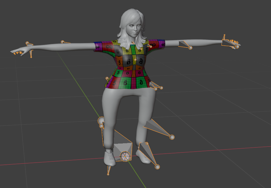
Once you’ve met the prerequisites, it’s time to open the .blend file and begin.
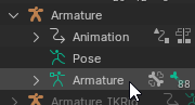
In the outliner you should see two objects:
the “Armature” and “IK Armature” (used for advanced animating)
We’ll only be focusing on the first rig for now. Make sure you're familiarized with the camera system as well.
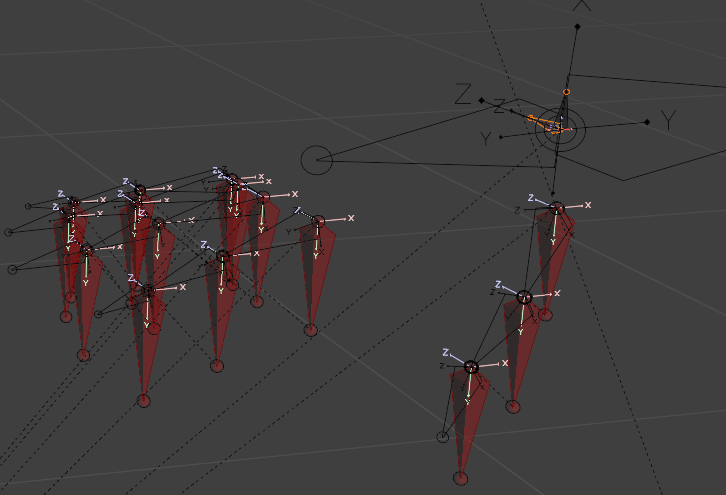
Step 1. Import your player model into the scene
For this guide I’ll be using the default playermodel for the mesh.
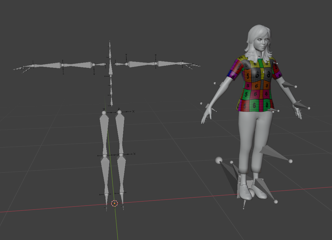
After importing, you’ll likely have your mesh parented to a new armature.
This will be the ‘old skeleton’. This will be useful for adjusting to fit the Tower armature.
If the bone directions are incorrect (like above) don’t worry, we’re only temporarily using them.
Verification
Before anything, we want to make sure the mesh has all the data we need.
Make sure the mesh has UV maps and they are visible in the UV Editor.
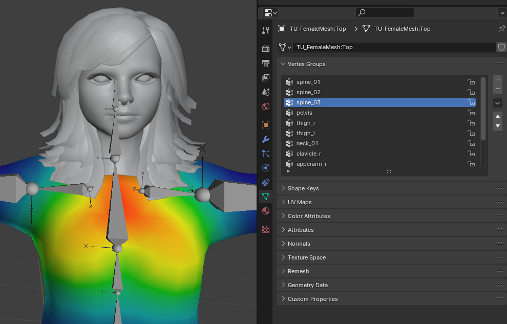
Also make sure the mesh has usable vertex groups in its Object Data Properties,
You want the groups to have visible weights in Weight Paint mode.
If no heat spots show (all blue), this means you have no weights.
You’ll have to paint them yourself, or use the automatic weighting and reparent.
Models from existing games should import with vertex groups automatically.
If the vertex groups on the mesh are named differently from the Tower Skeleton Hierarchy, leave them unchanged for now.
Setup Materials
After verifying the UV maps, we can setup the textures for our playermodel.
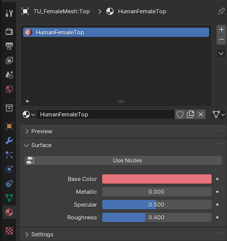
In the Material Properties you may already have slots created, if not, create them and assign the materials to the necessary faces.
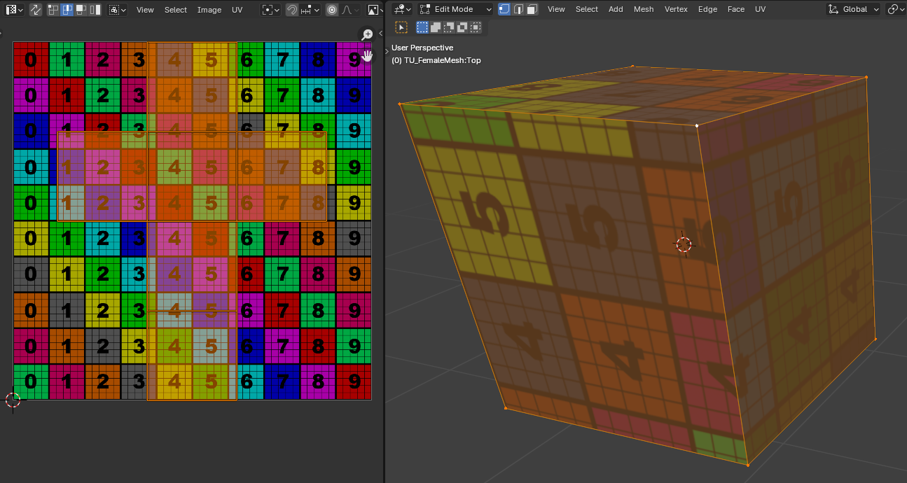
Here’s a quick demonstration with two materials, you can see the first material (green) is automatically assigned to the whole mesh.
 You can use Ctrl+L after clicking a vertice to select face groups much faster
Keep track of the names of the material slots, as they’re very important later for importing the model.
Technically, this is as far as you need to go for importing in-game to function.
The follow steps are only if you’d like to preview the textures in Blender:
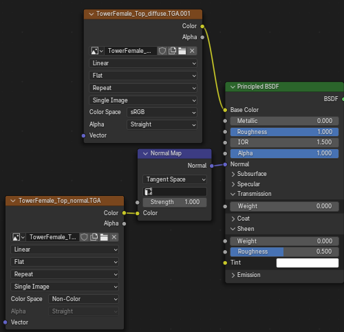
Drag out a new window and open the Shader Editor. You should see the below nodes if you have the material slot selected. Make sure to click ‘Use Nodes’ under the Surface tab in the Material Properties.
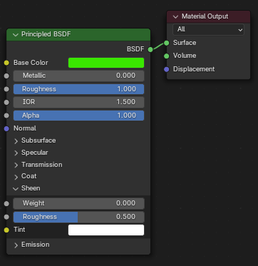
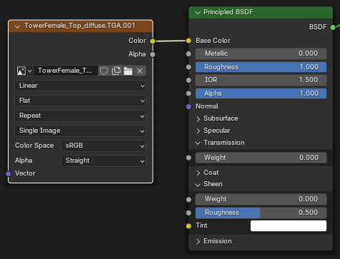
Right Click (or Shift-A) and click Texture > Image Texture, you’ll create a new node you can import your texture to.
You can select the texture by clicking 'Open' and browsing for it locally, or create a UV Grid texture by click 'New' and set 'Generated Type' to either UV or Color Grid.
Hook up the Color output of the texture node to the Base Color of the Principled BSDF.
In Material Preview, Render or Solid viewport shading (with ‘Color’ set to Texture), you should be able to see your texture.
For Diffuse textures with an alpha, hook the “Alpha” output of the image node into the BSDF alpha input.
Then, in the Material Properties, scroll down to the “Settings” tab and switch Blend Mode to ‘Alpha Clip’
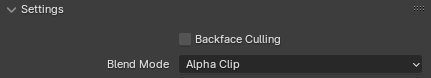
The alpha will appear correctly in Material Preview/Render viewport shading.
(Doesn’t seem to work correctly in Solid mode)
To preview your normal map, follow the same process, but hook the Color output of the normal texture’s image node to a Normal Map node (Shift-A > Vector > Normal Map)
You can then hook that node’s output to the Normal input of the BSDF.
You should now be able to see the Normal maps in Render or Material Preview shading.
- To preview these in the viewport properly, you may need to click off the image node (Just click the BSDF shader node) since in Solid shading, selecting specific image nodes will preview that node only.
Setup Armature Modifiers
Select all the meshes then go into the Modifiers tab. You may already have the modifier setup for you.
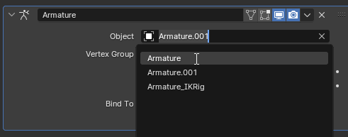
If not, add one through the “Add Modifier” dropdown, and set it to the old skeleton (in my case named Armature.001)
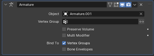
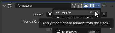
Note the display toggles next to the modifier title. You can hover over them for more info.
For now you’ll just need the monitor button enabled.
-
With multiple meshes selected, you can press Ctrl-L and then click ‘Copy Modifiers’ for ease, bear in mind it’ll replace the existing nodes.
-
When selecting from dropdowns (like the “object” one above) you can hold ALT while clicking to apply the change to all selected meshes with the same modifier, instead of only the active selection.
Step 2. Align the mesh to the armature
Now we must align the mesh to the Tower skeleton. We’ll use the old skeleton to make this easier for us.
If your mesh imports on a different axis from the armature, you can use the 3d cursor as a pivot to rotate and align the mesh with the armature. We want these to be +Z Up, -Y Forward.
- Select the mesh and old skeleton in Object Mode, and set the Transform Pivot Point to the 3d cursor.
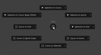
- Use the Shift-S hotkey to open the cursor snap radial menu. Select ‘Cursor to World Origin’ to snap the cursor where we need it.
- Rotate the two objects to align with the Tower Skeleton. You can type in the desired values and axes to use. [shown in the gif]
- Afterwards, apply the transforms (Ctrl-A > All Transforms) on the two objects to ensure a smooth export.
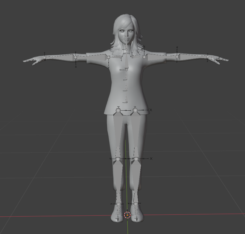
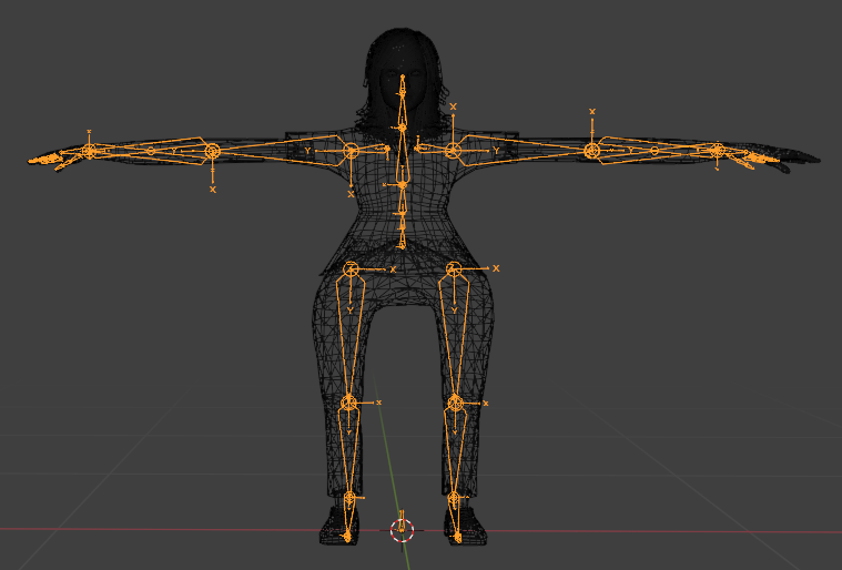
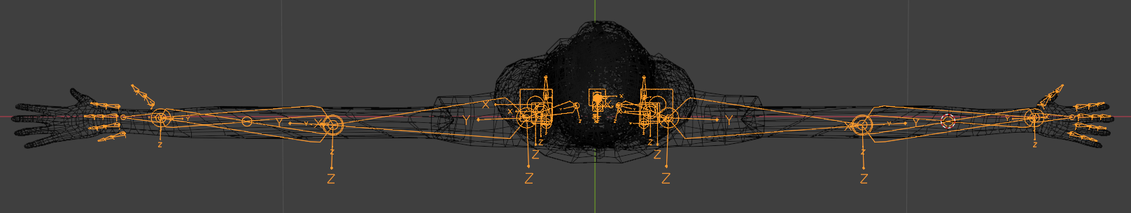
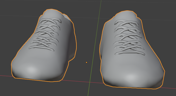
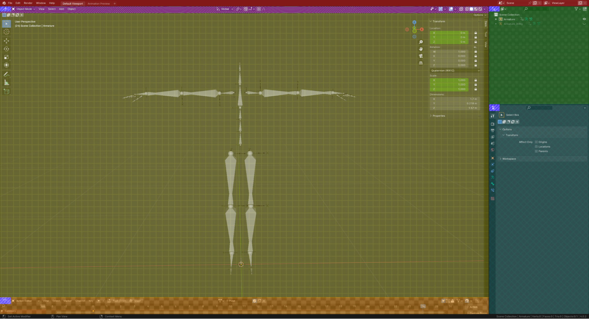
For some models they might import in an ‘A-pose’, like shown:
We need the models to match the Tower Skeleton’s ‘T-Pose’.
- Select the old imported armature in object mode, then go into Pose mode.
- Then use the old skeleton to transform the bones to a T-Pose, matching the Tower pose.
Here I selected all the mesh objects (and the old armature lastly) then went into wireframe mode for easier visibility.
Step 3. Adjusting Proportions
It’s very likely your character will have different proportions. As of v3, you can adjust the Tower skeleton itself to any lengths you want.
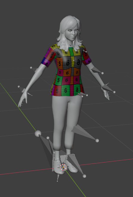
For example, if the imported mesh looks like this:
Then we must adjust the Tower skeleton to fit these proportions by editing its bones manually in Edit mode.
We want to avoid changing the bone angles for the Tower Armature, only the bone lengths.
The further off the bone angles are, the more warped the in-game animations will be.
Use the mirror option next to the sidebar in the viewport to save some time. 
This should work fine with the Tower Skeleton, but might be buggy with your import skeleton. Be wary!
Keep in mind you can use the normal transformation orientation to help keep the bone angles retained.
If certain bones (like the twist bones) are getting in your way, you can hide them either by:
- Selecting the bones and pressing H to hide them. (and Alt-H to unhide)
- Or hiding the twist bones collection.
-
When adjusting proportions, be sure to move the gun_# bones alongside the hand_# bones, as well as the ik_knee and ik_elbow bones with their respective limbs! [not shown in the gifs]
It will be much easier adjusting them now rather than later.
(OPTIONAL) To correct twist bones, I use the 3d cursor to get the midpoint of the bone length, then grab the middle heads of the twistbones, and snap them to the midpoint.
Don’t worry if the bones don’t line up exactly, we’re only focusing on getting the proportions correct.
We’ll adjust the skeleton more precisely in the following step.
If you need to adjust the IK joint bone positions, you can use Snap > Vertex, then transform on a single axis, and then select the elbow point.
You may need to hide your mesh so it won’t conflict with the snapping.
For the gun bones, grab the middle-point of your hand bone with the 3d cursor, and snap the gun bone to this point.
Move it downward by -2.5cm (by typing in the values, which wasn’t shown in the gif) or eyeball it however you wish.
The ik_foot_# bones of the armature have a Bone Constraint set to automatically lock to the tails of the calf bones.
This should position them automatically for you. The only important caveat is that they must align with the foot bones at all times. If you change the foot bones for your model, be sure to adjust these IK bones as well to compensate.
All these IK bones are important as they will be used for in-game IK functions, in the near future we’ll use these particular bones for in-game foot IKs for example.
This is optional and not necessary for exporting to the game, it's purely for animation.
Matching the Tower Skeleton
At this point the Tower Skeleton should roughly match the proportions of your playermodel.
It’s likely your playermodel won’t match the Tower skeleton, like varying limb or finger positions.
The mesh I’m using has improper symmetry, you can see the hands are uneven and out of place.
We have a couple options at our disposal to correct this:
Utilize the Mirror modifier
In the scenario above, since the right arm is (mostly) correct, we can delete the left arm and use a mirror modifier for correct symmetry.
Just make sure both directions of vertex groups are listed on the mesh object (*_l and *_r), and the mirror modifier comes before the armature modifier.
In Pose mode, pose the old import skeleton to match the positions of the Tower bones.
This is where the old skeleton becomes very handy.
Since the mesh is currently rigged to the old skeleton, we can transform the mesh to fit the Tower skeleton, then apply the changes in later steps.
If your model has longer fingers, you can also edit the finger bone lengths of the Tower Skeleton the same way as Step 3:
Keep in mind you can use the normal transformation orientation to help keep the bone angles retained.
This is where warping would be most obvious with animations like holding weapons.
Use proportional editing on the mesh in Edit mode.
We can force the vertices on the mesh itself to the correct position.
This will break any usage with the old skeleton, so make sure to apply the changes you made with it before this method, and be absolutely sure that you won’t be needing it again.
Testing Animations
If you’ve finished making changes using the old skeleton:
First you should ensure the meshes’ vertex groups are named according to the Tower Skeleton hierarchy.
You won’t be able to test animations until the vertex groups match the new skeleton.
If you plan on making more changes using the old skeleton, you can change its bone names to match the hierarchy as well.
(With the old skeleton’s bones renamed, you can switch the hook object of the Armature modifiers between the two skeletons easily. This will let you make adjustments using the old skeleton, and testing the results much quicker.)
When ready, apply the modifiers hooked to the old skeleton, so all of the modifications you made in earlier steps are finalized.
You’ll have to recreate the armature modifiers, but you can do this quickly by creating new ones, then using Ctrl-L > ‘Copy Modifiers’ to clone the mods of the actively selected mesh to all selected meshes. Keep in mind this will replace any existing modifiers (like mirror)

Alt-Click to switch the ‘hook object’ of all selected objects (with the same modifier) at once.
By this point the hook object of the Armature modifiers should all point to the new Tower Skeleton.
- Select the ‘Tower Armature’ object in Object Mode. (The new skeleton)
- Change the action in the action editor and we can see the results.
Press Spacebar to play/pause your animation.
When finished, switch it back to the ‘T-Pose’ action
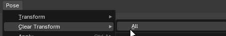
(or click the  button next to the action, and in the Header Bar, Pose > Clear Transform)
Then we re-assign the meshes back to the old skeleton (if you plan on using it more to adjust), and return to Step 3 or 3A. You’ll want to continue adjustments until you’re satisfied with the rigging.
Or, if satisfied, keep the meshes hooked to the Tower Skeleton, and continue with the guide.
After this stage your model should conform to the Tower Skeleton, and function well with the animations.

You can now delete the old skeleton as we won’t be needing it after this point.
Reset Bone Rolls
Once you’ve finalized your bone positions:
Select all of the bones in Edit mode, and press Shift-N to open the Bone Roll menu. Select the Global +Y option.
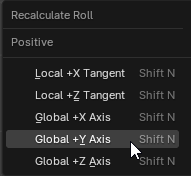
This ensures the bones are on the correct axis.
All bones must conform to this axis!
Very often, especially while editing bones, the roll will change. This should be done to all bones at least once before exporting, to ensure no unexpected rolling issues will crop up.
Step 4. Advanced Rigging
This section contains guides for optional rigging solutions.
You can skip to the export step if you feel your model is ready to go.
Twist Bones
Twist bones are optional corrective bones for meshes pinching at extreme twists. The process for creating them is simple, as we just take the original bone weights and split it into two halves.
Out of all the twists, the most important twists are the lower arm twists, as they’ll be the most visible in-game, specifically for first-person arms.
The others are mostly correctives you won’t really notice in most circumstances.
To utilize twists, first you must duplicate the original vertex groups twice.
For this example, we’ll create lower arm twists.
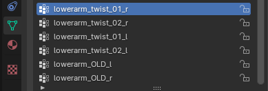
Rename the duplicated groups to lowerarm_twist_01_[d] and 02, and rename the original groups to anything. In this case I just added “OLD”.
You must rename the original groups, or else they’ll override the twist bones. Never delete them, in case you need them as a backup.
It would be wise to click the “lock” icon next to the old groups so they will not be changed.
The sets of three vertex groups should have identical weightmaps at this point.
(I’ve hidden the large “lower arm” bone in the above example for easier visibility)
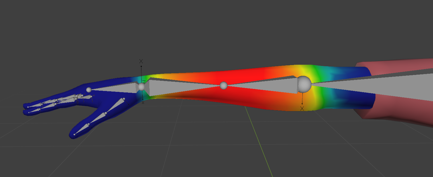
In Pose mode, we can rotate our hand bone to see the twists in action:

The above example doesn’t have correct weights yet, notice it’s twisting the entire forearm.
All we have to do is split the weights in half according to the twist bones. We can easily accomplish this using the Gradient tool in Weight Paint mode.
Switch to Weight Paint mode, and click the gradient tool. You’ll find it in the Toolbar [ T ].
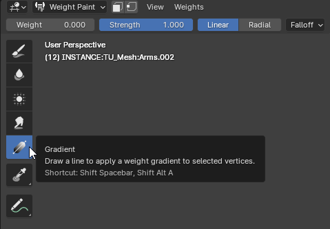
With the Weight set to 0, and Strength set to 1, mask out the halves for each twist.
The simplest way is to go into Orthographic mode (clicking -Y on the Gizmo), then dragging the tool from one bone end to the other.
Hold SHIFT while doing so keeps your selection line straight.
Then, go to the “Weights” menu and click “Normalize”
In this example, we’re creating the twist 01 bone (closest to pelvis)
Then we mask the twist 02 bone from the opposite direction.
For each set of twists, you can obtain decent results using this method. You may need to change where you start/end your gradient selection and adjust accordingly depending on your mesh’s topology.
With the lower arm twists, I’d recommend dragging the gradient across most of the arm, rather than the two ends of the bone.
 This example above is painting the 01 twist weight.
With the same process on the 02 bone, the final result should look similar to below:
Remember to ‘normalize’ the weights for the twists.
This averages out the weight range for the map, so the twists take better effect
We can test our changes by rotating the hand bone (or using the IK Armature)
Use the other paint tools (or retry the gradient tool) to adjust as necessary.
(You can also adjust the weights after rotating the bones, which allows you to see the weight changes live.
Just be sure to reset the hand rotation afterwards when you’re finished painting, so it exports correctly.)
Step 5. Export
With everything ready to go, we can now export the model as a .dae and import the model into the game.
Before we export, be sure:
- The “Armature” is named Armature (specifically the Armature node)
- The Armature uses the correct hierarchy, and that there is only one root bone.
- The Armature is hooked to the mesh using the Armature modifier
- The Bone Rolls are reset to Global +Y
- Material Slots are named correctly
- All objects have their transforms applied
- Your textures should respect the guidelines listed here.
Unfortunately Blender’s native .dae exporter is very old and very broken, but it will function for most uses. These are issues you’ll need to keep in mind:
-
The exported .dae will only store the material paths pointing towards the diffuse texture, and ignores any other texture, like normal maps. (We work around this further down the guide.)
-
Meshes MUST be parented and stored inside the Armature object like below:
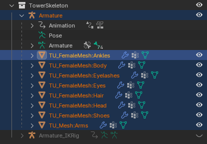
Failure to do so will break the .dae and create duplicate armatures, you won’t be able to import it.
Select all the objects you want to export, which would be “Armature” and any meshes hooked to it.
Go to File > Export > Collada (.dae)
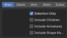
Under the “Main” tab, click “Selection Only” and make sure the other options are unchecked.
Under “Geometry” have “Apply Modifiers” checked, and “Triangulate” unchecked.
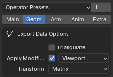
Use the Triangulate modifier on your object instead, the .dae exporter doesn't work correctly.
You can then export the file.
It’s wise to open a fresh .blend and import the .dae you just exported to make sure nothing broke or duplicated during that process. Just make sure you set up the scene identically so you don’t have scaling issues.
Textures & Paths
For textures, store the files in the same folder as your .dae. The game will search for them when importing and assign them based on the naming format.
The supported material maps and their associated names are as follows:
Diffuse maps: <Material Slot Name>_Diffuse.<file type>
Normal maps: <Material Slot Name>_Normal.<file type>
Height maps: <Material Slot Name>_Height.<file type>
So if you had a material called "MetalArmor" for your model, and you used .pngs, your textures would look like:
MetalArmor_Diffuse.png
MetalArmor_Normal.png
MetalArmor_Height.png
Step 6. Importing Into Tower Unite
Now with the .DAE exported, you can import the model into Tower Unite's Player Model Editor.
To access the player model editor, go to the Main Menu of Tower Unite. Near the bottom, there is a Workshop Editor option. From there, click on Player Model/Item Creation.
Once in the editor:
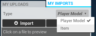
- Select the My Imports tab.
- Select Player Model from the dropdown.
- Click Import.
- Select the .DAE file from wherever you exported it.
Your model will then be converted into our in-house format (.model).
If it fails for any reason, a log will be output under the Compiler Info tab. You can read the entire import process and troubleshoot any issues that come up.
Step 7. Metadata
You can also further edit your player model for Tower Unite specific features using the metadata editor.
The metadata editor allows you to adjust player scale, wearable offsets (hats, backpacks, etc.), and various material properties.
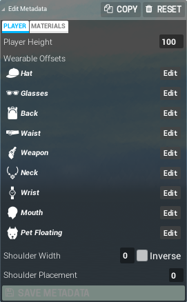
Shoulder Width / Height
An option from the legacy workshop models.
This will allow you to offset the shoulders in two directions. This has been made obsolete (but usable) with Workshop 3.0
Material Metadata
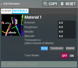
You can adjust the material settings using the metadata editor.
- Emissive: How much the material glows.
- Roughness: Strength of the material's reflection.
- Metallic: How metallic the material is.
- Specular: Reflectiveness of the material.
- Transparency: Adjusts if the material is partially translucent or masked (masked takes in lighting and does not have as many visual sorting issues)
- Toon Shader: Applies a cartoon effect on the material.
When viewing your imported player model, you can also preview animations and the capsule collider using the tool bar at the bottom right of the editor.
Step 8. Publishing
To publish your Character, select the My Imports tab, and make sure that Player Model is selected.
Once you have done this, you should see a list of all of your imported characters.
Find the character that you wish to upload, and click on its name. On the right, click on the big blue upload button. From there, you will see the upload panel.
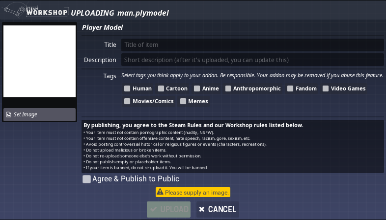
Fill out the necessary information, tag your character appropriately, and follow our rules. Failure to do so will result in removal of your workshop model.
Once you have filled out all the information, simply click Upload, and the editor will upload your model to the Steam Workshop!
If you want to make your playermodel immediately public, click the Publish & Make Public check box then hit upload, otherwise leave it unchecked and you can make it public from the published Workshop page.
You can update your playermodel's title, description and images on the published Workshop page, but to update your tags or thumbnail, you will have to do a full update to your playermodel.
Upload Errors
If your character failed to upload to the Steam Workshop, it will give you an error message:
- Nothing: Sometimes this just happens. Try uploading once or twice again, before investigating further.
- Title / Description: Large bodies of text in the title or description field may prevent the upload. Keep it short or empty and you can update it freely afterwards.
- Maintenance / Downtime: Sometimes Steam Workshop is taken offline (generally weekly on Tuesday afternoons) and will be unable to accept uploads. If this is the case, try again in 15 minutes or so.
- Bans: If you have recently had an item removed from the Workshop, you may be limited by a temporary Workshop ban, even if it wasn't a Tower Unite item.
- Restart: If all else fails, the tried-and-true restart may help.
If none of these options fix the problem, you can ask for help in our workshop channel on Discord.
Updating
To update an existing workshop character, click the My Uploads tab in the item editor.
From there, you will see a list of your uploaded workshop addons. If you do not see any uploaded Workshop addons, check if you are properly connected to Steam or click 'Get My Uploads'.
Find the item you want to update and click on it. An update dialog will open up, and will automatically populate with existing information of the playermodel for you.
From here, you can update the title, the image, tags, and the file.
To update the model, click on Select File To Update and select the file from the list that pops up.
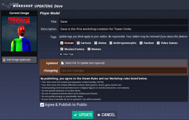
Once you are done with your changes, click Update, and the editor will send the changes to Steam Workshop.
IK Armature
The IK (Inverse Kinematics) Armature is used for animation. It automatically positions bones to a target point.
Compared to FK (Forward Kinematics) where you have to rotate each bone individually, it can make it much easier to animate.
This is currently unusable for anything in-game at the moment, but the ability to create custom animations is planned in the future.
For now the current animation rig is included for your own personal use, and to help you get familiarized with the concepts.
Although be warned the IK rig is likely subject to heavy changes in the future, so be wary if you'd like to create animations for the game before we implement custom animations, they could end up broken.
To enable IK functionality, you’ll find a control panel above the IK rig.
In Pose Mode, Drag the ‘Enable IK’ slider towards ‘on’ to activate.
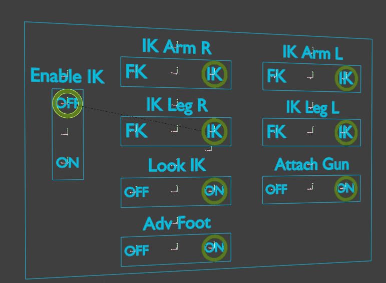
These are the features you can toggle:
-
IK/FK Limbs
Switches limb solver for case-by-case use (a swinging arm is easier in FK than IK) -
Look IK
Rotates head to face the IK eye target at all times
-
Attach Gun
Keeps the Gun_# bones attached to the hand bone
-
Adv Foot
Advanced foot placement, enables easier foot rolling and toe curling
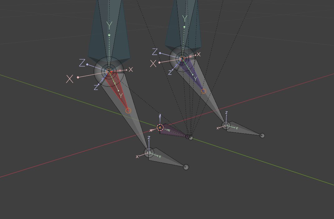
Modifying the IK Armature
If you’ve modified the proportions of the Tower Skeleton, you’ll have to adjust the IK Armature bones with the same methods mentioned previously.
In Edit Mode, first position the 3D cursor at the head of the bone.
In this case we want the head position of the hand bone:
Then, we’ll snap the IK Armature’s equivalent to the 3D cursor position.
Take note of the “Structural Bones” bone category. It’s hidden by default, but contains bones used for certain IK operations. You’ll have to reposition these bones the same way.
The wrist driver bones pictured above can be difficult to see
Now the ‘IK Arm’ is properly repositioned, but you’ll have to repeat the process for each changed bone (like the fingers) with the same process.
The feet are a little more complicated, as they also have driver bones setup for more complicated actions like foot-rolling.
You can reposition these the same way fairly easily, since they line up with the default bones (besides the heel bone, but that just needs to be moved to the mesh’s heel, wherever you feel.)

Blender Glossary
3D Space
We use 3 axes to calculate in three dimensions: X Y Z
We set positive and negative values for an Up, Right, and Forward axis, which varies by program.
This makes up our location (and by extension scale) values in our transform.
The scene/world has a static transform all objects inherit from (known as global/world-space)
The standard we use for world-space (in Tower) is +Z Up (positive) and -Y Forward (negative).

You can view the world axis with the viewport Gizmo.
Rotation is calculated by combining axes together in a specific order, known as ‘Euler’ angles.
Unreal uses an XYZ Euler. X (Roll) - Y (Pitch) - Z (Yaw).
This will be more relevant if you choose to create animations in the future. (when supported)
Transforms
Scenes (and your objects) all have their own transform (scale, rotation and location) values in 3d space. You can see these values in the transform menu.
These all stack in a hierarchy based on a parent/child relationship.
The scene has a (typically) static transform (known as global/world-space),
Your objects are parented to the scene, and contain their own transform space (known as local-space),
Children of those objects inherit their parents’ transform, and so on.
These “origins” are represented by a small orange dot when you select an object.
We perform a transform operation by selecting the object in the viewport and pressing either:
- G - Move
- R - Rotate
- S - Scale
And then X Y or Z for the desired axis.
(To edit multiple axes, hold Shift and then the axis you want to exclude)
Then you can perform your operation based on the Transform Pivot selections.
Either use the mouse, or type in the exact values to adjust
Then Left-Click to accept the changes (or Right-click to cancel)
You can also enable and use object gizmos if you’d prefer visual handles you can grab.
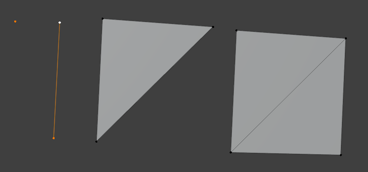
Apply Transform
In Object mode, most transform operations add the values you set on top of the object’s base transform.
To zero out/apply the transform:
In the viewport, select the object, press Ctrl-A, then Apply the transform.
(Or go to Object>Apply in the Header Bar.)
You’ll see the Transform values reset to 0 (or 1) while retaining your modifications.
You can run into issues exporting if you have mesh/armature objects with varying transforms, which is why you want to make sure they’re all zeroed out beforehand.
Objects
An ‘object’ is a container that stores its own local transform coordinates, as well as a ‘data-block’
A data-block is a mesh, material, image, armature/skeleton, basically any resource.
When an object links to a data-block, it's marked as a 'user' of the block. You can have any number of objects in the scene linked to one specific data-block.
Objects are listed in the Outliner, and their assigned data-block in the Object Data Properties.
Data-Blocks and Users
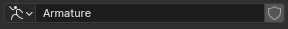
Next to most name inputs, you can click the  shield icon to assign a Fake User. This preserves the data-block if it's not linked to any objects when cleaning up the file. (File < Clean Up < Unused Data Blocks)
This might seem a little tedious to understand, but it's important to know the distinction between an object and data-blocks so you don't give yourself issues down the line.
I highly recommend cleaning up fairly often and keeping good track of the data-blocks and their users so you don't clutter and bloat the file size of your blender file.
You can look at what’s stored in your blender file by changing the Display Mode in the outliner.
Resources Glossary
Textures/Materials
A texture is an image that projects onto the mesh’s UV map.
- Albedo/Diffuse textures are the raw image file that’s displayed on-screen.
- Normal Map textures warp incoming light. This is used to project high detail onto low poly.
- Specular/Roughness textures control glossiness.
Texture resolutions are measured and scaled by power of 2 values, like 128x128 or 512x512.
Larger textures drastically increase memory usage, it's very important to be mindful of the sizes and make them as small and efficient as possible. You don’t need eyeball textures that are 2k (2048x2048) for example.
It’s recommended to keep your resolutions at or below 1k (1024x1024)
Textures are stored in “Material Slots” in the Material Properties menu.
Armature
An armature (also known as skeleton) is a hierarchy of bones that structure the mesh it’s assigned to.
These are used to animate your playermodel.
The “Armature” object stores another “Armature” data-block, which contains our skeleton.
The skeleton structure uses a parent/child relationship, with the first bone being a parentless “root” bone.
You can only have one root bone, and any bone chain must connect to the root.
At the moment you cannot add extra bones, so the blend file provides all you need for the armature.
Tower Skeleton Hierarchy
This is the strict naming convention for the Tower skeleton. All bones here must be correctly named and parented for importing to function correctly.
If your model doesn’t use certain bones, it’s recommended to delete them.
The only caveat is that you cannot delete bones without also deleting any children bones attached to them. (So Hand_R cannot be deleted unless you also delete the finger bones as well)
There can only be one root bone, so make sure all chains are children of the root bone.
Bones listed will be labeled as:
*bonename_(d) [parent bone]
‘d’ (direction) means there will be two bones with ‘l’ (left) and ‘r’ (right) variants
For example: thigh_l and thigh_r
Bones marked with an asterisk (*) are twist bones, which are optional corrective bones.
We go over how to use them in the linked section, otherwise you can ignore or delete them.
 ‘Armature’ Object (can be named anything)
 ‘Armature’ Node
root
ik_foot_root	[root]
ik_foot_(d)		[ik_foot_root]
ik_elbow_(d)	[root]
ik_knee_(d)	[root]
pelvis		[root]
	spine_01 [pelvis]
		spine_02 	[spine_01]
			spine_03	[spine_02]
				neck_01	[spine_03]
					head		[neck_01]

				clavicle_(d) 	[spine_03]
					upperarm_(d)		[clavicle_(d)]
						*upperarm_twist_01_(d)	[upperarm_(d)]
						*upperarm_twist_02_(d)	[upperarm_(d)]
						lowerarm_(d)			[upperarm_(d)]
							*lowerarm_twist_01_(d)	[lowerarm_(d)]
							*lowerarm_twist_02_(d)	[lowerarm_(d)]
							hand_(d)			[lowerarm_(d)]
								gun_(d)			[hand_(d)]

	thigh_(d) [pelvis]
		calf_(d) 		[thigh_(d)]
			*calf_twist_01_(d)	[calf_(d)]
			*calf_twist_02_(d)	[calf_(d)]
			foot_(d) 		[calf_(d)]
				ball_(d) 		[foot_(d)]
There are three finger bones each parented in a chain: hand_(d) → *_01 → *_02 → *_03
index_0#_(d)
middle_0#_(d)
ring_0#_(d)
pinky_0#_(d)
thumb_0#_(d)
Mesh
A container for polygons. These are the shapes that make up our model.
In Blender this is named ‘mesh data’, which links to a mesh object.
This container also stores UV maps, Materials, and Vertex Group data.
Most models have multiple meshes that piece together. Like a ‘shirt’ mesh, ‘pants’ mesh, and ‘head’ mesh.
Otherwise, the entire model might be inside one mesh.
Vertexes
A vertex is a specific point in 3d space.
It also acts as a container that holds various values, like vertex normals and vertex weights.
All 3d models are composed of “vertices”, and connect like a web to make polygons/faces.
UV Maps
UV maps are coordinates set in the mesh for textures to project onto.
We unfold a 3d shape in 2d space similar to a cardboard box, or an origami figure.
We mark ‘seams’ along edges in Edit mode, and unwrap the UV map in the UV Editor.
Vertex Weights/Groups
Each vertex stores normalized (0 to 1) values called ‘vertex weights’.
‘weight’ refers to how much the vertex will follow the specified bone.
Vertex groups are named identical to the armature’s hierarchy, and is the container for all the vertex weights of your mesh.
In Weight Paint mode, “heat spots” represent the weight values of the group.
The vertices will turn blue (0 weight applied) if it’s not assigned to the selected vertex group. The closer to red, the stronger the influence.

Blender Interface
This is the Blender interface. The highlighted parts are referenced throughout the guide.
The image has been color and pattern coded for easier reference. You can right-click and open the image in a new tab for better visibility.
Top Bar - Red Flat
Interface Selection - Blue Stripes (In Any Window Corner)
Outliner - Green Polkadot
Header Bar - Purple Waves
Properties Menu - Blue Diamond Grid
Viewport - Yellow Square Grid
Action Editor - Orange Checkerboard
The status bar at the very bottom contains useful context info when performing an operation.
Right-Clicking it shows a menu for enabling scene statistics and other file info.
Top Bar

Contains standard dropdown menus, as well as Workspace tabs.
Workspaces
The v3 .blend file is set up with two workspaces, the 'Default Viewport' and 'Animation Preview'.
- You will do most of your operations in the Default Viewport
- Switching to the 'Animation Preview' workspace gives you a cleaner layout to test animations, with a more prominent action editor, and pins the properties menu to the armature's object data properties.
Any Interface Window
Splitting Windows/Editor Type
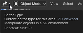
This option is visible for every interface window, it's the general list of main interfaces in Blender.
Most of what you need is already visible, but you may need to split new windows to switch to other editors, like the UV Editor for texture mapping, or the Dope Sheet for the Action Editor.
If you click and drag the rounded edges of any window outward, you can split the active window. Dragging the corner of a shrunk-down window inward towards an edge will collapse the window.
Outliner
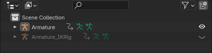
Each entry you see in the outliner is an ‘object’ in the scene.
Objects act as containers that store data-blocks assigned to it.
You'll see "Armature" and "Armature_IKRig" stored in a "Scene Collection" (Blender's equivalent of folders)
Parent/Child Object Relationships
These objects are sorted by a parent/child relationship. If you click the triangle to the left of the name, it'll reveal what's parented to the object.
In this example, we have various mesh objects parented to the Armature object:
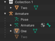
Mesh object One is contained directly inside the armature, Mesh object Two is indirectly parented, contained in a separate collection.
Holding SHIFT while dragging an object around in the outliner, and hovering it over other objects will reveal hotkeys for various parenting operations.
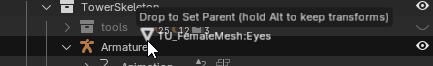
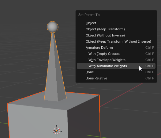
You can also select multiple objects in the viewport (which are highlighted orange) and then press Ctrl-P to parent them to the last selected object (highlighted in yellow), and Alt-P to unparent them.
This will give you a menu with more options. For example, trying to parent a mesh to an armature will allow automatic bone weight/vertex group generation.
Display Mode
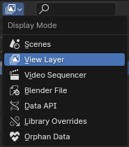
This dropdown gives you a list of information displays about the blender file itself.
The most relevant ones at the moment are:
‘View Layer’ - Lists the objects in the scene. (scenes can have multiple view layers, we only need one)
‘Blender File’ - Lists all the assets stored in the Blender file itself.
Outliner Filter
At the top of the outliner, you'll see a Funnel-like icon to the left. Click for a dropdown menu.
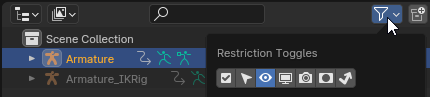
This menu controls Restriction Toggles. These are the most relevant ones:
 Exclude from View Layer: Hides objects that are unchecked in the outliner. You might notice the hidden "shapes" collection (this is used for the IK rig, not important in your case)
![]() Disable Selection: Allow selectability in the viewport
Disable Selection: Allow selectability in the viewport
 Hide in Viewport: Quickly hides the object (does not reduce lag)
 Disable in Viewports: Fully disables objects in viewport (best used for intensive objects that lag, might also be a culprit if you can't find a hidden object.)
Header Bar

Object Interaction Mode
Interaction Modes
Dropdown for switching between various interaction modes
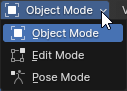
Object Mode is the root interaction mode, used for selecting objects and transforming them in the viewport.
Edit Mode
Edit Mode is for manipulating the selected objects. (Default hotkey is Tab)
- For meshes you edit vertices/faces and other mesh-specific operations
- For armatures you set the default bone positions (also known as the 'rest' position).
Pose Mode
Pose Mode (visible when selecting armatures) is for testing meshes that are hooked up to the selected armature, and keying actions/animations. (Default hotkey is Ctrl-Tab)
- You might notice the bones turn different colors. The bones have various constraints (Properties menu > Bone Constraints) that are hooked up to the IK Armature.
Weight Paint Mode
Weight Paint Mode (visible when selecting meshes) is used for painting rigging data to the mesh, like legs, hands, head, etc. for the armature to use.
The mesh shows “heat spots” representing how much the vertices are weighted to the selected group.
Transform Pivot
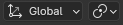
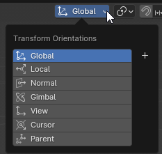
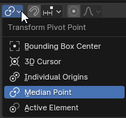
This changes the axis of your transform operations.
By default, our transform operations move based on the ‘Median point’ of your selections.
Pivot Point changes the location of the hinge, Orientation changes its rotation.
Using the 3D cursor as a Pivot
You can use the 3D Cursor as a reference point in a transform operation, for example:
Set the Transform Pivot Point to the 3D Cursor
Then use the Shift-S radial to snap the cursor to the ‘world origin’
Now when you transform your selections, it’ll rotate around the cursor/world origin, as opposed to the Median point.
Visibility Dropdowns

These menus control visibility for a lot of contexts within the viewport.
The most important ones to know about are the ‘Show Gizmo’ and ‘Show Overlays’ menu
Gizmos are visual tools for various objects
Overlays are visual assists for the viewport.
You can click these buttons to disable them globally.
For example disabling ‘Show Overlays’ is useful if you just want to see the visible meshes by themselves.
Viewport Shading
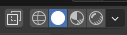
These buttons switch to various visual modes. Hold Z in the viewport for a radial menu shortcut.
You can hover over each option for more info.
You will typically use the wireframe and solid modes.
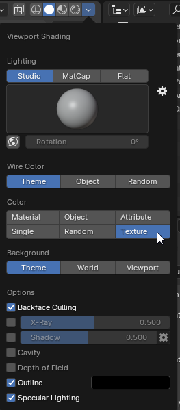
The dropdown on the right shows settings for the active shader. You can change the scene lighting and background, along with other various visual options.
In solid mode, it’s recommended to enable “Texture” Color so you can actually see your textures.
(material uses a separate viewport color and is misleading)
As well as enable ‘Backface Culling’, which shows the rendered side of a face only, rather than making them two-sided.
Properties Menu
Multi-purpose menu, this is where you configure settings for the world, scene and objects, apply modifiers and constraints, and much more.
The top half of the tab bar controls world and scene settings.
Output Properties and Scene Properties
This is where you configure the project settings listed earlier.
The second half of the tab bar contains settings for the last selected/pinned object.
Object Properties
This section is general settings for the object container itself, like transform info (which you can also find in the Viewport Sidebar typically).
Modifier Properties
This section lists ‘modifiers’, which are various crucial tools and operations that hook into the object.
These apply in order from top to bottom.
On the top row, each one contains display toggles that affect visibility in the viewport, like the outliner filter.
(You can hover over them for more info)
The most important ones will be the “Mirror” and the "Armature" modifier.
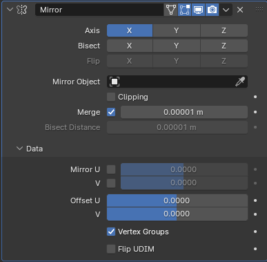
This duplicates the object and flips it (like a mirror). Refer to the example below.
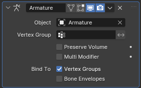
This hooks into mesh objects and directs it to use the specified armature.
-
With multiple meshes selected, you can press Ctrl-L and then click ‘Copy Modifiers’
This will clone the mods of the active mesh to all the selected meshes, bear in mind it’ll replace the existing mods. -
When using dropdowns like the “object” one here, you can hold ALT while clicking your selection to apply your changes to all selected meshes with the same modifier.
Mirror Example
You can create the right arm only, and using this modifier, it’ll automatically duplicate the left arm and apply the vertex groups accordingly.
You’ll need to make sure the vertex groups are all listed, and the mirror modifier is before the armature.
( Right arm has *_r weights groups painted, *_l groups are blank but listed.
The mirror modifier mirrors the *_r weights to the blank *_l groups automatically. )
Object/Bone Constraint Properties
This section is used for various transform operations. You'll use this tab if you intend to modify the IK Armature later on down the line, otherwise you can disregard this tab.
Object Data Properties
This section of the properties menu edits the selected data-block. It changes depending on the object type.
At the top of the menu, you’ll see a text slot with a shield at the right.
This is the data-block linked to the object.
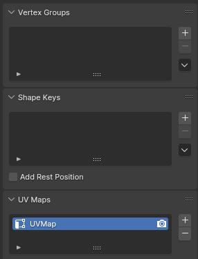
Meshes have vertex groups, shape keys, and UV Maps.
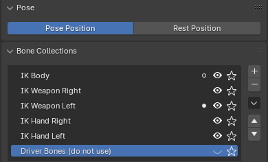
Skeletons have the Bone Collections and Pose toggles.
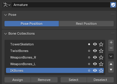
-
The Pose/Rest Position toggles are used to switch between the selected armature's ‘Edit mode’ root pose (T-Pose) and the ‘Pose mode’ pose (typically the selected action in the Action Editor).
-
The Bone Collections are visibility toggles for bone groups. The important groups are the Default Skeleton Hierarchy and Twist Bones.
-
The Custom Properties dropdown in the 'Armature' object contains toggles used for the IK Armature.
Material Properties
This section contains the material slots used for textures.
We create slots here, and hook textures up to a shader in the Shader Editor. Refer to the Setup Materials step for more instructions.
Viewport
3D previewer for all the objects in your scene. (so long as the relevant display filter is enabled)
Using the Viewport Camera
Holding Ctrl and Middle-Click (Mouse3) zooms the camera in and out.
Alternatively you can use the Scroll Wheel.
Holding Shift and Middle-Click (Mouse3) pans the camera.
Holding Middle-Click (Mouse3) orbits the camera around its focus point.
You can reset the focus point by selecting an object, then pressing Numpad Period.
(You can rebind keys in the Edit > Preferences menu if you do not have a numpad)
Alternatively there are options to lock the orbit point in the ‘View Lock’ section of the View Tab
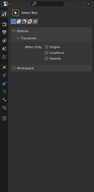
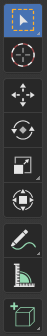
Toolbar
Pressing T will show you a toolbar of various operations depending on your interaction mode.
(I'll tell you the hotkey equivalent typically)
Sidebar
Pressing N in the viewport reveals the Sidebar, you'll see a menu with tabs listed vertically along the edge. These are the sections relevant for you:
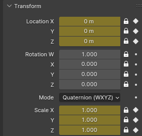
Item Tab
Displays transform information for the selected object. This menu is useful for precise adjustments or to see if your transforms are fully applied/zero'd-out quickly. (Scale is 1, and no Location or Rotation values).
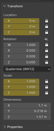
(You can also check these values in the Object Properties tab with the object selected.)
View Tab
View Settings
Controls your viewport camera settings.
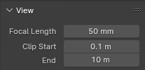
Focal Length: Controls the camera's Field of View (FOV).
Although you can set the focal length FOV in Blender to 90°, it doesn't reflect identically in Unreal (for whatever silly reason).
With experimenting, it seems setting it to 40mm is roughly the same as 90° in Unreal.
Clip Start/End: Controls the culling distance for models in the viewport.
(I set my Clip Start around 0.1 m, lower tends to get clipping artifacts.)
Don't set your Clip End value too high, or you may get performance issues in Blender.
3D Cursor Settings
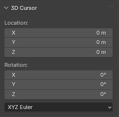
Manually edit the values of the 3d cursor.
Gizmos
This is a visual display of your scene’s orientation in 3D space.
If you do not see this, you can enable it through the  Gizmos dropdown on the header bar, and clicking the ‘Navigate’ checkbox.
You can click the dots on the gizmo to lock the camera to that axis.
You can also enable gizmos for objects here.
This will let you transform objects in the scene without using hotkeys.
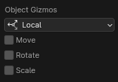
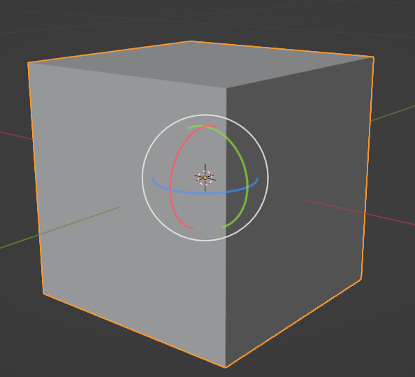
If you hold CTRL while dragging, you can enable snapping for more precision. (or type in the values)
3D Cursor

The 3D cursor is a floating point set manually either by:
-
Holding Shift and right-clicking in the viewport
-
Editing the values in the View tab in the sidebar
-
Pressing the 3D cursor button in the Toolbar.
-
Or Holding Shift-S in the viewport to open the cursor snapping radial menu
The cursor is very useful as a transform pivot, so you can manually set the hinge point for a transform operation.
Action Editor

This window is found by selecting the Dope Sheet Editor Type, and changing the mode dropdown to ‘Action Editor’.
- Either click the ‘Animation Preview’ tab, or select the armature object and go to its Object Data Properties.
- Make sure the pose state is set to ‘Pose’ Position and not ‘Rest’.
- With the armature selected, in the Action Editor, click the
 dropdown to the left of ‘T-Pose’, and change the action to whichever you choose.
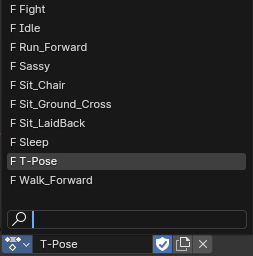
The blend file contains various animations you can test with.